Section VIII · Schematics & Cutaways
Visual Architecture
Engineering plates from across the program — cutaways, grid topologies, propulsion arrays, and terraforming engines, each a working reference drawing.
The doctrine, rendered
Engineering plates spanning the program — reactor cutaways, grid topologies, propulsion arrays, and terraforming engines. Each drawing is a working reference, not an illustration.
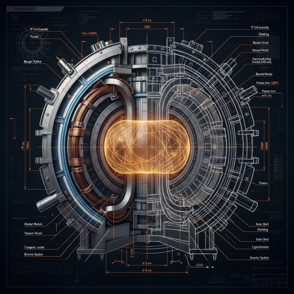
Cross-section through the confinement stack — plasma torus, superconducting coils, cryogenic jacket, tungsten first wall, and outer containment shell.
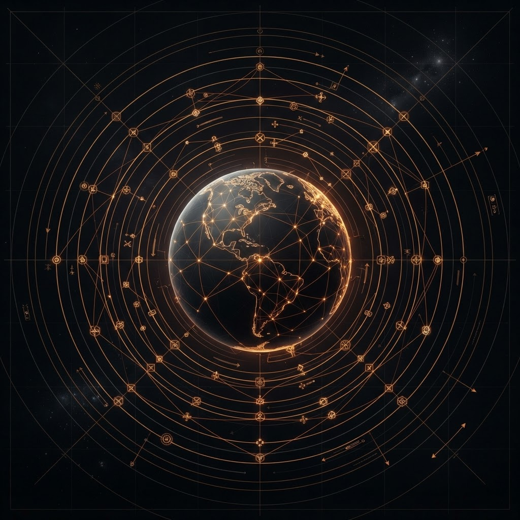
Planetary distribution nodes linked to orbital relay rings across the supergrid.
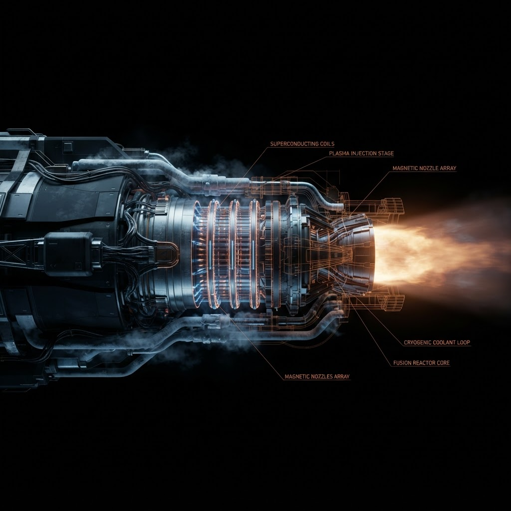
Voyager-class thrust channel with magnetic nozzle and confined plasma exhaust.
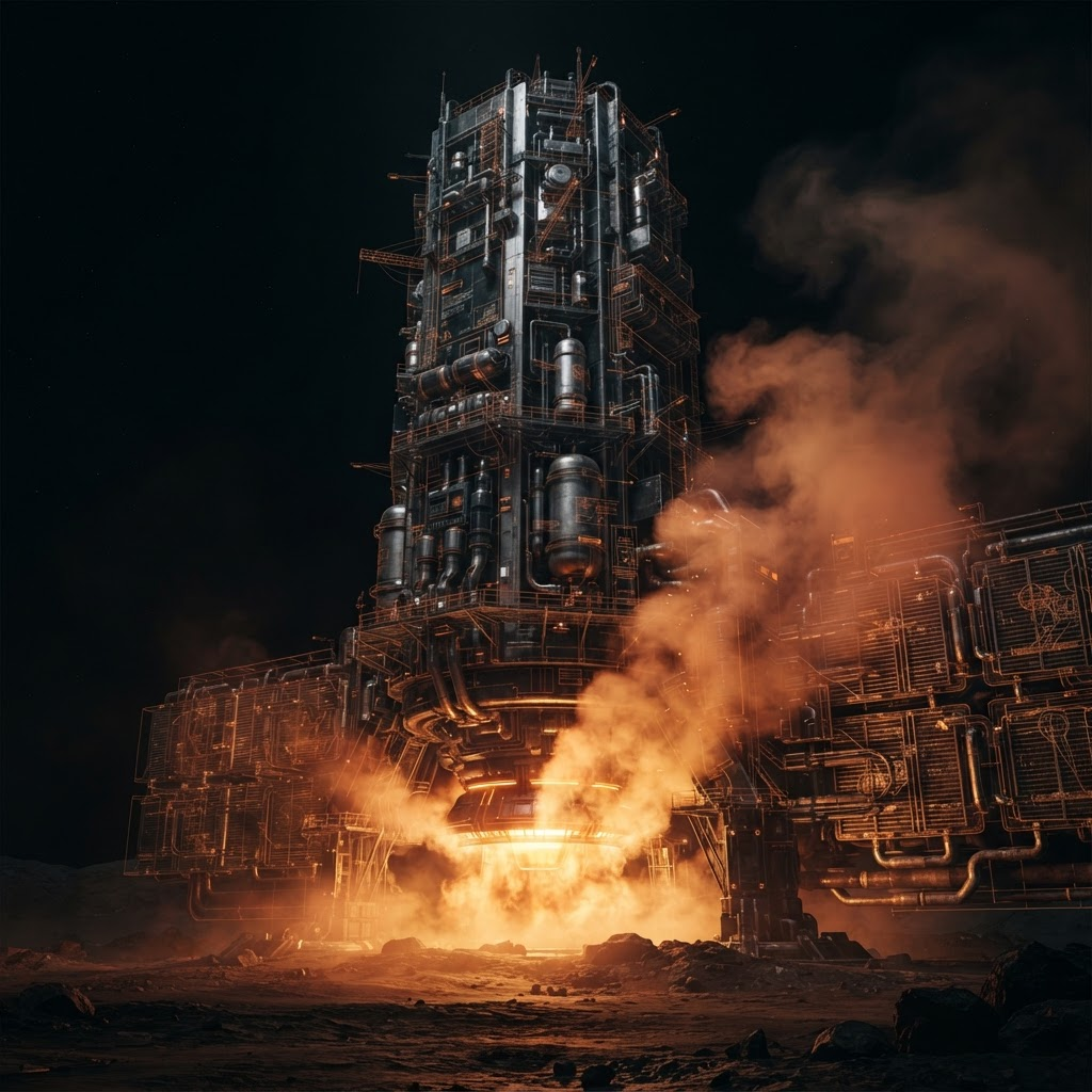
Martian atmospheric processor drawing continuous baseline power from a buried Radiant Core.
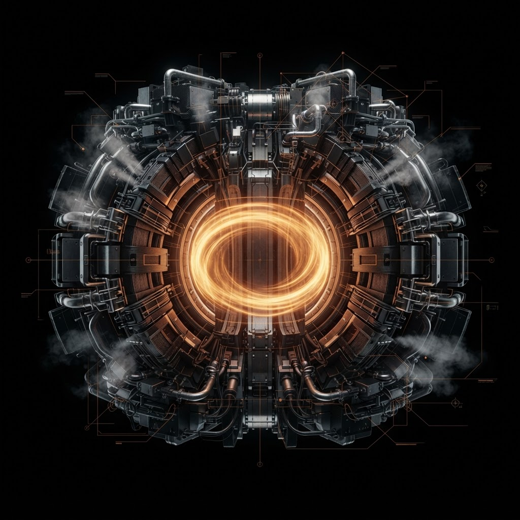
Full toroidal confinement assembly, magnet arrays and cryogenic spine integrated.